 RSS Feed
 Twitter
New Layout Board
My second attempt at a layout board has been completed and the measurements added for frames 1 through 6. Frame 0, the transom, is not on there yet because that frame is going to take some additional thought before laying out.
That is because, the transom is mounted at a 12 degree angle from vertical and the drawing has some notes about the transom being shown true size and having to adjust for the angle. Since I havent studied that part yet, I felt it best to wait until I understood better where the measured points will be.
At this point, I am ready to start re-doing the initial fitting of Frames 5 and 6 and make the corrections necessary for those frames. Then I will examine the other frames and also make any corrections needed for those. I will not be able to do Frames 1 and 2 because I do not have enough lumber to complete them yet. Probably later this year or after the holidays since mahogany is fairly expensive.
Here is one photo of the layout board. There are a few more images in the photo gallery (link in upper right corner of the blog site).
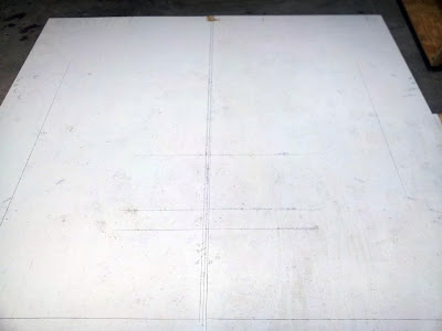
The line at the bottom of the photo is the baseline where all vertical measurements are taken from. The layout board is actually two pieces of plywood connected together. You can see the joint in the center of the picture. Just to the left of that are two vertical lines. The one closest to the joint is the centerline (the other was the first centerline but it was too far left). The centerline is used for all horizontal measurements.
The center line is 90 degrees perpendicular to the baseline but looks a bit off when compared to the joint because the baseline is not exactly parallel to the edge of the panel. This is fine as long as the center line and the baseline are exactly perpendicular to each other. I took great pains to insure this was so. The other marks are the chine, sheer, keel points as well as some other reference lines that will be needed later.
The various points are determined by measuring up from the baseline and left or right from the centerline. All points are labeled for later use. So until next time.......
0 Response to "New Layout Board"
Post a Comment